Experiments
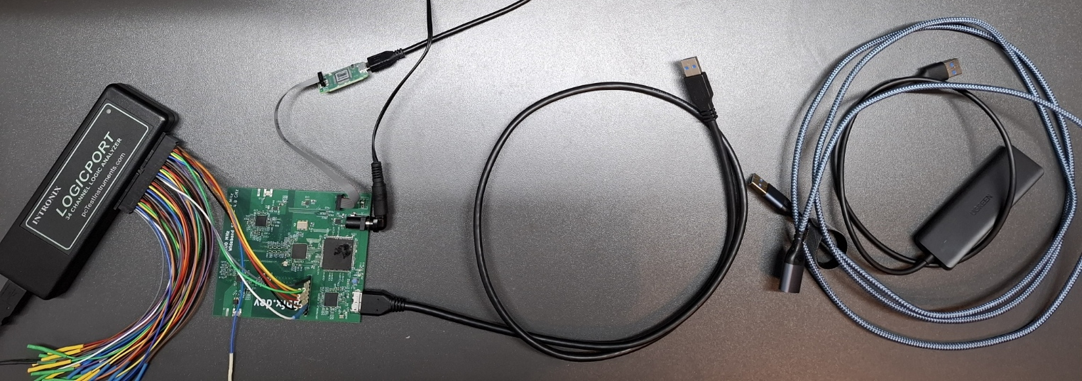
My setup for the experiments is a custom FT601Q PCB with Intel MAX10 FPGA, a normal 60 cm USB cable into a USB Hub into a 2 m USB extension cord to a Windows 11 PC. This means there is a combined 3 m of cable between the PC and the PCB which should make for a sufficiently challenging setup. Signals are logged with a logic analyzer.
Code for the software is posted with the experiments below, also check out the official “Data Streamer Demo App”.
One-way throughput PC->FTDI
Writing data from PC to FTDI is quite simple on the FPGA side, because we can just set RD_N and OE_N low and the FTDI will shuffle data out as fast as it can. On the software side, we can use blocking or non-blocking API calls.
Code:
|
|

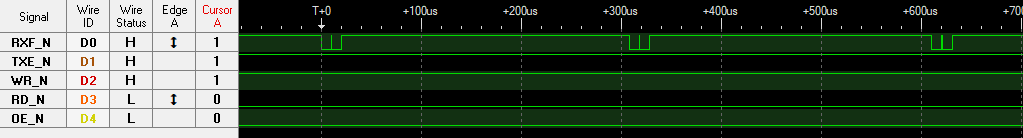
Waveforms using blocking API calls

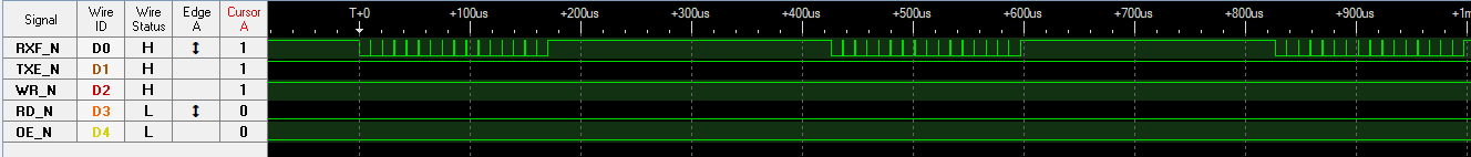
Waveforms using non-blocking API calls (quad-buffering)
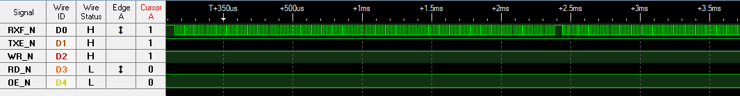
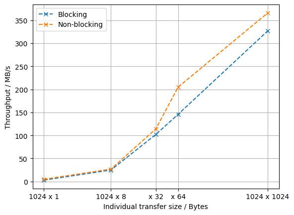
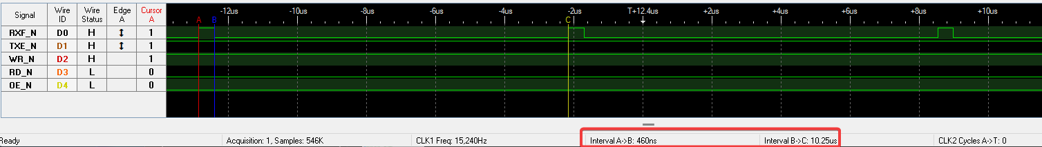
Some waveforms for the different transfer setups are behind the spoilers above. For the smaller transfer sizes - where transfer size refers to the buffer size passed to an individual call to FT_WritePipe() - we see relatively long gaps (~250 µs) between chunks of data arriving at the FPGA. On top of that, after every 4 KB, there is a small pause (see below) in the data output, likely because the FIFO inside of the FTDI is 4 KB in size.
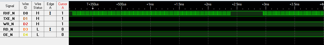
We can optimize the throughput by reducing the impact of the time (~250 µs) that every API call seems to be taking at minimum, by using the non-blocking API to submit further transmission to the queue before the last one ends. Additionally, it helps to choose a large buffer size in each API call. The “saturated” waveform at full capacity is shown below, where the FTDI outputs data for 10.24 µs (1024 cycles -> 4 KB) and then needs around 460 ns to start this process again. This leads to a maximum throughput of $ \frac{4~\mathrm{KB}}{10.24~\mathrm{µs} + 460~\mathrm{ns}} = 374~\mathrm{MB/s} $.
One-way throughput FTDI->PC
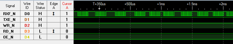
One-way throughput from FTDI to PC shows similar behavior as the other direction, i.e. performance increases with larger buffer and using the non-blocking API. However, the saturated traffic pattern (at least in my case) is slightly less regular and the time between every 4 KB filling of the FIFO is slightly longer than above, leading to a slightly lower maximum throughput of 346 MB/s.
Two-way throughput
For two-way throughput, I’m not listing values here because results heavily depend on how often the direction is switched, how many cycles are allocated to reverse the bus and how big the chunks of data in each direction are.
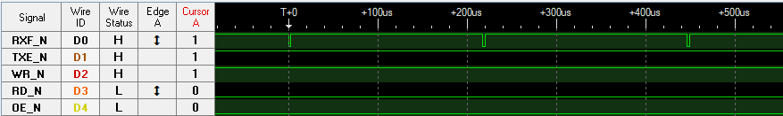
Roundtrip time PC->FTDI->PC
This test first writes 20 bytes from PC to FTDI, then receives 20 bytes from the FTDI. There are two variants of this on the software side. The first uses the naive approach of FT_WritePipe() and then FT_ReadPipe() such that the read request is only submitted once the WriteRequest is done. The first variant pre-loads an overlapped FT_ReadPipe() before dispatching the write, such that the read pipe should already be open once the write completes.
Code:
|
|
Result:
|
|
We reach around 500 µs roundtrip time, independent of which variant we use. This is likely due to a couple hundred µs being used within each of the driver calls, which is why the overlapped approach brings no benefits. However note that it does make a big difference in terms of throughput.
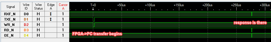
Roundtrip time FTDI->PC->FTDI
This experiment covers scenarios where data is acquired on the FPGA and sent to the PC via the FT60X, then some or most processing is performed on the PC and depending on the processing, results are sent back to the FTDI. So here we will first receive a block of 1024 bytes via FT_ReadPipe() and afterwards send a response via FT_WritePipe(), measuring the time until that response arrives at the FPGA. Since the reading is completed before the writing in this case, there’s no need for the overlapped variant.
Here, we can achieve around 275 µs from beginning to send out the 1024 bytes until we receive an answer at the FPGA, which seems like a decently fast roundtrip time for a non-realtime system.