Overview

A Local oscillator (LO) is required for analog frequency conversion (mixing) and is therefore part of most analog radio frontends. An exception to this are direct conversion architectures which perform frequency conversion in the digital domain and can therefore use a digital LO (NCO).
While free running LOs are thoretically possible, most real life systems require frequency stability and accuracy that is hardly realizeable without locking to some more or less stable frequency reference. That reference is typically a “low frequency” (few tens of MHz) crystal or MEMS source and the locking mechanism is typically a loop built around a frequency divider and phase comparator (PLL - phase locked loop). The loop contains a high frequency oscillator which is then locked to an integer or even fractional multiple of the reference frequency.
To make this setup usable in an analog circuit, we can use the output of the frequency-locked oscillator as our LO. An alternative and somewhat more recent approach is to use this output as a clock signal for a digital circuit with a high sample rate DAC, which then generates a sinusoid at its output. The latter approach is called Direct Digital Synthesis (DDS).
Luckily, there are a couple of “go-to” PLL and DDS ASICs that are offered from China as inexpensive, small, self-contained modules on eBay, AliExpress, etc. When prototyping RF circuits, these modules can cover many LO needs! This post lists the most common modules and their performance, as well as advantages and disadvantages.
| Part | Type | module cost (€) | fundamental frequency range (MHz) | fundamental output power | considerations |
|---|---|---|---|---|---|
| Si5351 / MS5351M | locked loop | < 3 | 0 - 200 | +8 dBm | Extremely cheap; very simple I2C interface; “only” to 200 MHz; even harmonics can be a pro or con |
| ADF4350 ADF4351 |
locked loop | 20 - 25 | 138 - 4400 35 - 4400 |
up to +4 dBm | Huge frequency range |
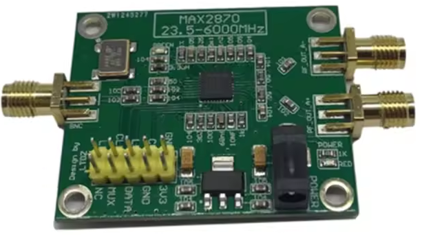
| MAX2870 | locked loop | 50 - 90 | 24 - 6000 | More expensive alternative to ADF435x with even larger frequency range, less common | |
| AD9854 | DDS | 55 | 0 - 150 | -13 dBm | Very high frequency resolution; high sweeping speed; I/Q output; PCB setup requires using parallel interface which can be a annoying to wire |
| AD9910 | DDS | 60 | 0 - 400 | -5 dBm | 1 GSPS; very high frequency resolution; high sweeping speed; no Q output |
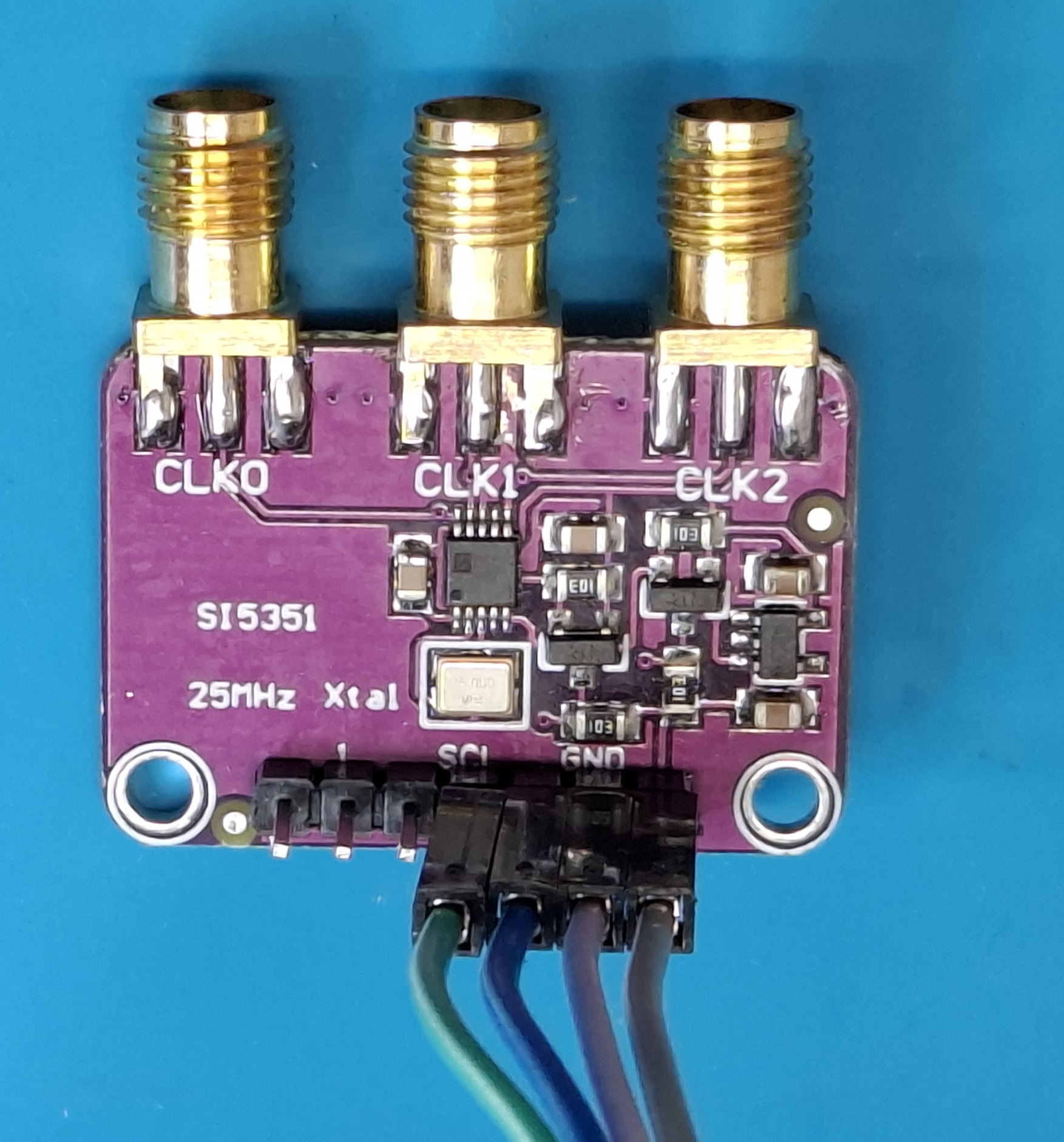
Si5351 / MS5351M
The Si5351 has risen to fame in the ham radio scene because for a just a few $/€, it can generate reference-locked frequencies up to 200 MHz, covering the radio bands up to 2m. You can find many ham radio designs built around this chip as well as in-depth analyses and measurements on the internet (e.g. NT7S). The chip’s popularity has lead to the creation of clones, as the one linked above. If you buy one of the “Si5351” modules on the internet, unfortunately you should expect to get a clone, and not an original chip. From what I can tell, they work fine regarding their basic function, but I wouldn’t count on them reaching the same performance as the original.
There are a surprising number of advanced features in these chips, which can make a manual configuration of the registers a bit tedious. Additionally, I wouldn’t count on all of the advanced features even being implemented in the cloned chips. If you just want to create a few quick frequencies, I can recommend the “ClockBuilder Pro” software, which can generate the complete register map for you.
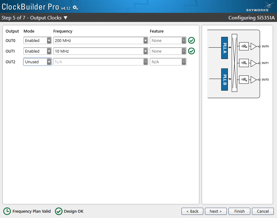
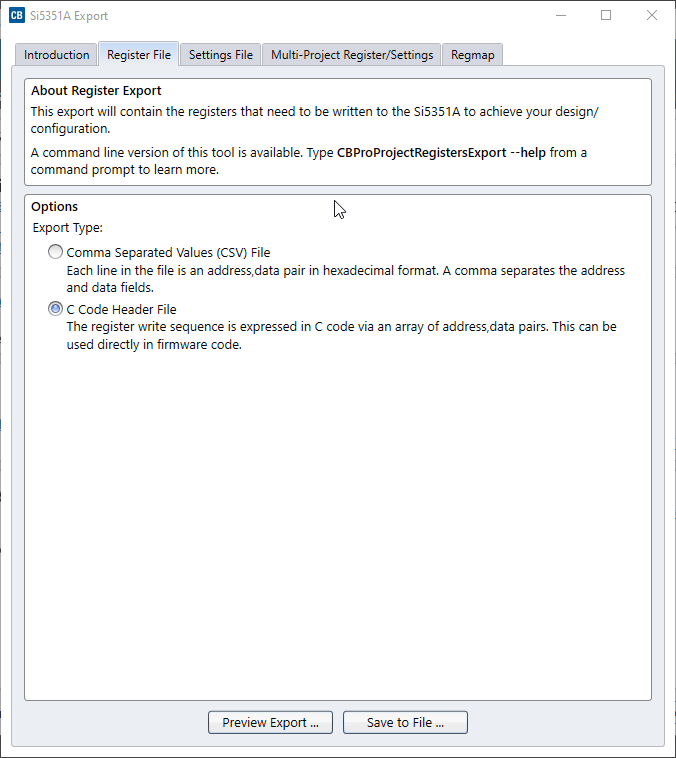
The registers can then be programmed through a simple I2C interface, shown here on an STM32:
|
|

ADF435x
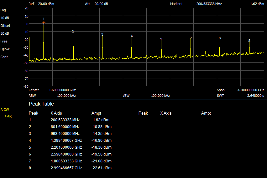
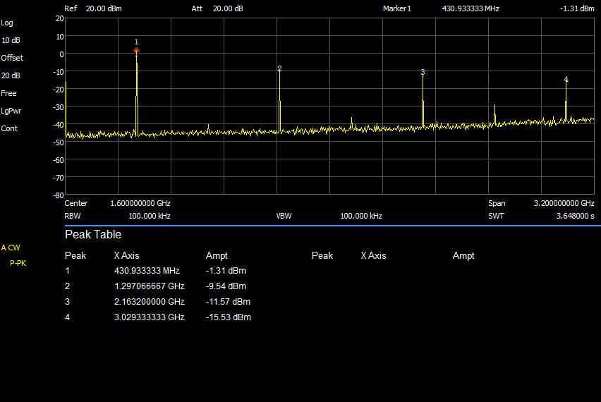
The ADF435x are a bit more expensive than the Si5351 but can also go much higher in output frequency. The ADF4351 starts at 35 MHz while the AD4350 starts at 138 MHz, so if that range is important to you, make sure to get the right one, although it has happened to me that I ordered a 4351 module on eBay but got a 4350 instead. Compared to the Si5351, there is a bit of additional complexity because the ADF435x use an external loop filter, which can have an impact on the required register values. In my experience, the loop filters on the modules from China are directly taken from the original reference design / eval board and seem to work well over the entire frequency range. You can use the Eval Board software provided by Analog to quickly generate register values for any configuration.

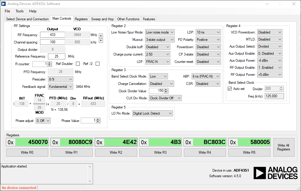
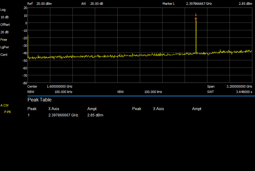

The registers are then programmed via SPI, shown here for an STM32:
|
|
DDS modules
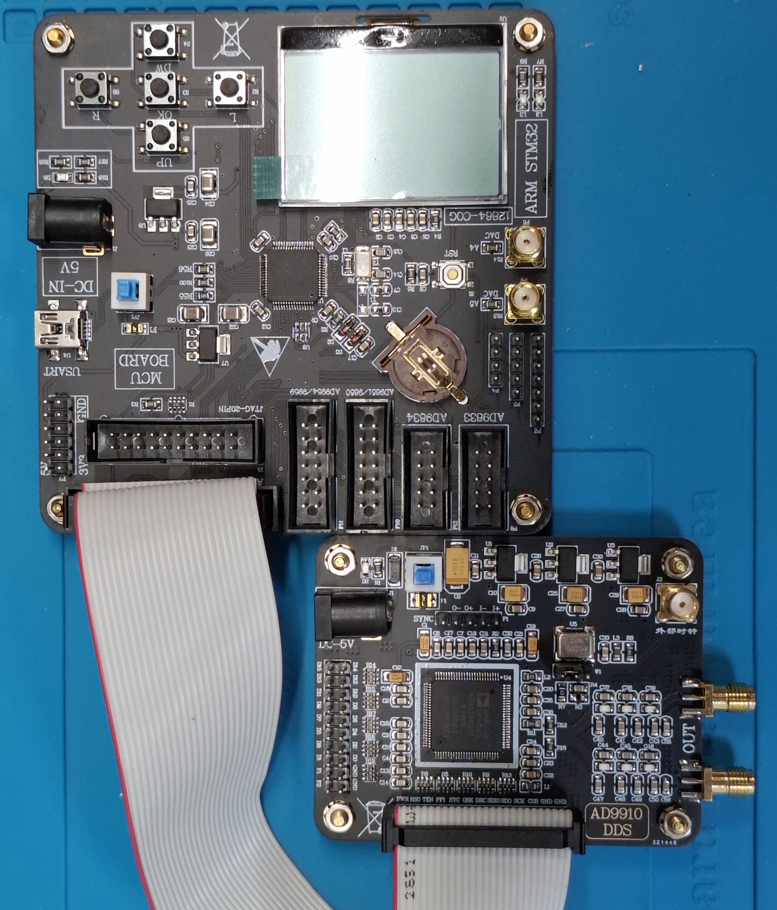
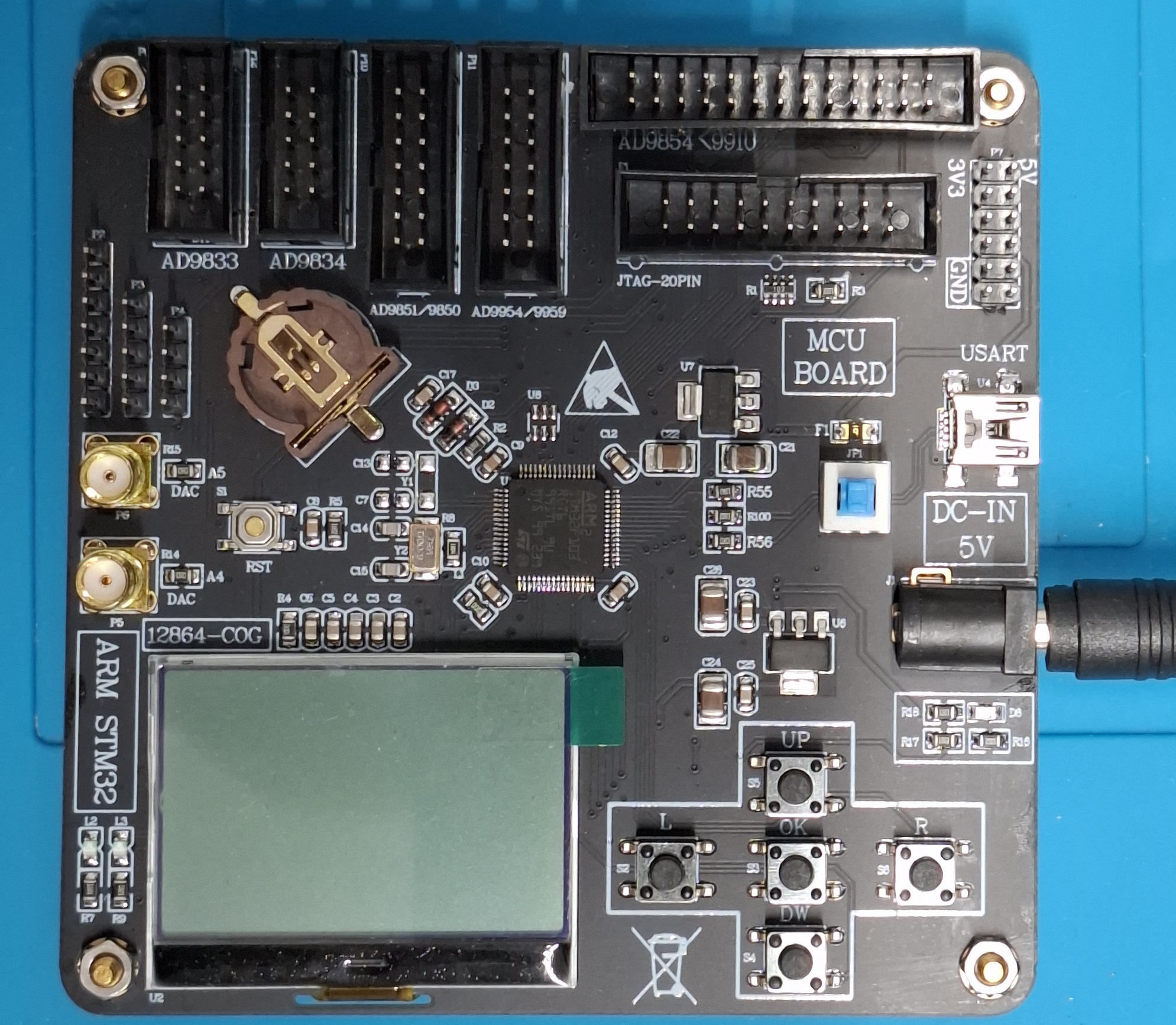
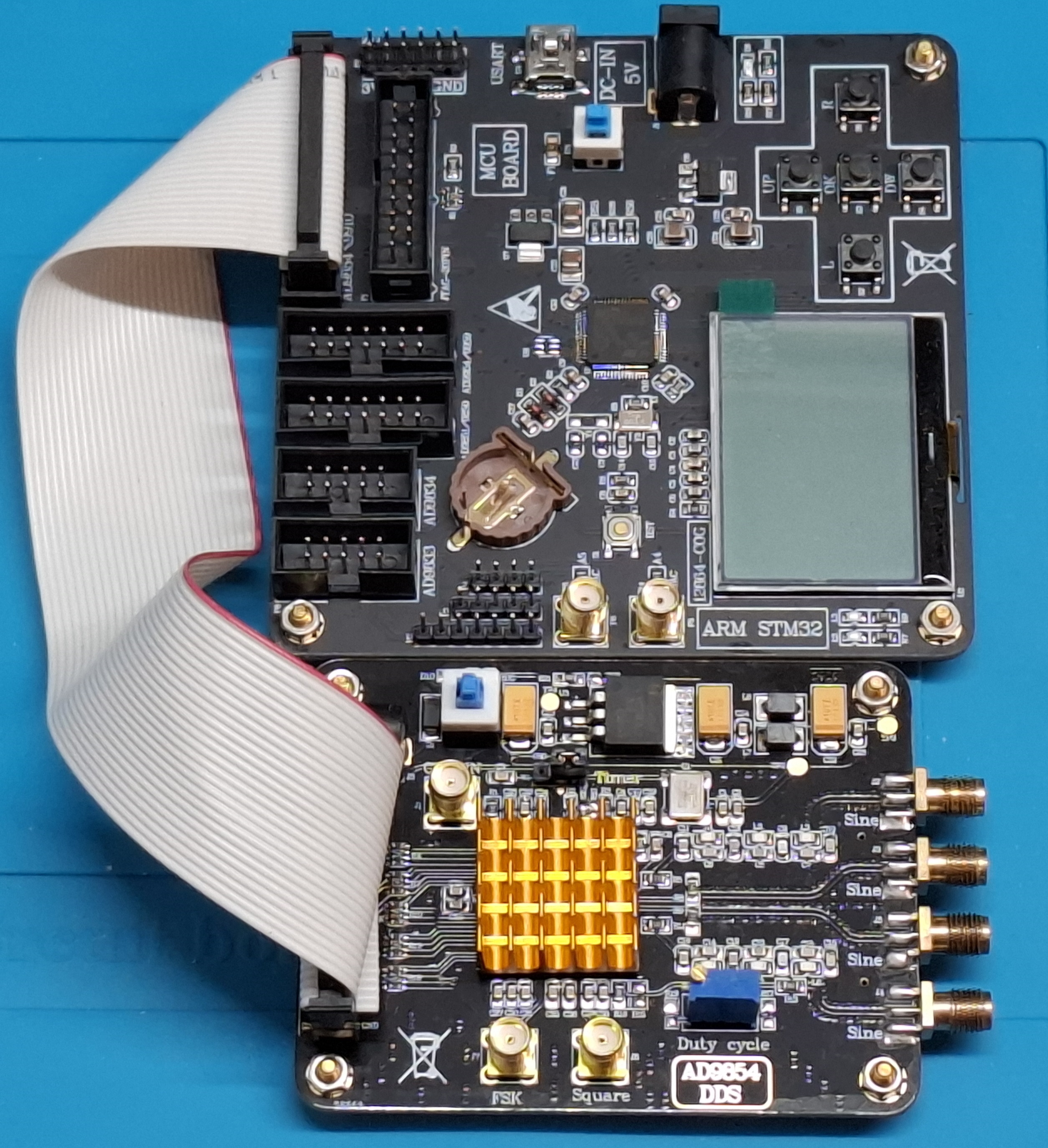
Driver board
The same sellers selling the DDS modules typically also offer a “DDS driver module” (or similar). This board is offered for around 25€ and contains ribbon cable jacks to connect to the various DDS boards, and an STM32 with a screen and buttons to control them. However, the pre-flashed firmware didn’t work with my AD9854, so I ended up flashing my own code onto it, without actually using the screen and buttons. However, if you intend to use one or more of the DDS modules, especially via the parallel interfaces, it might be worth the money because it keeps the wiring tidy.
If you have an image of the stock firmware, please let me know.
The chip on the driver board is an STM32F103RCTx and you can easily set up a project for it in STM32CubeIDE. The pinout for AD9854 and AD9910 is shown below. If you have the pinouts for other compatible DDS modules, please leave a comment!
Expand pinout Table for driver board
| STM32 | AD9854 | AD9910 |
|---|---|---|
| PC0 | D0 | |
| PC1 | D1 | DRHOLD |
| PC2 | D2 | DROVER |
| PC3 | D3 | IO_UPDATE |
| PC4 | D4 | PROFILE[0] |
| PC5 | D5 | PROFILE[2] |
| PC6 | D6 | PD |
| PC7 | D7 | PLL |
| PC8 | A0 / SDIO | OSK |
| PC9 | A1 / SDO | SYNC_CLK |
| PC10 | A2 / IO_RESET | PROFILE[1] |
| PC11 | A3 | TxENABLE |
| PC12 | A4 | PSO |
| PC13 | A5 | EXT_PWR_DWN |
| PA2 | OSK | SCLK |
| PA4 | UNCLK | DRCTL |
| PA5 | WR | SDIO |
| PA6 | DDS_RESET | MASTER_RST |
| PA8 | RD | SDO |
| PB10 | FSK | CSB |
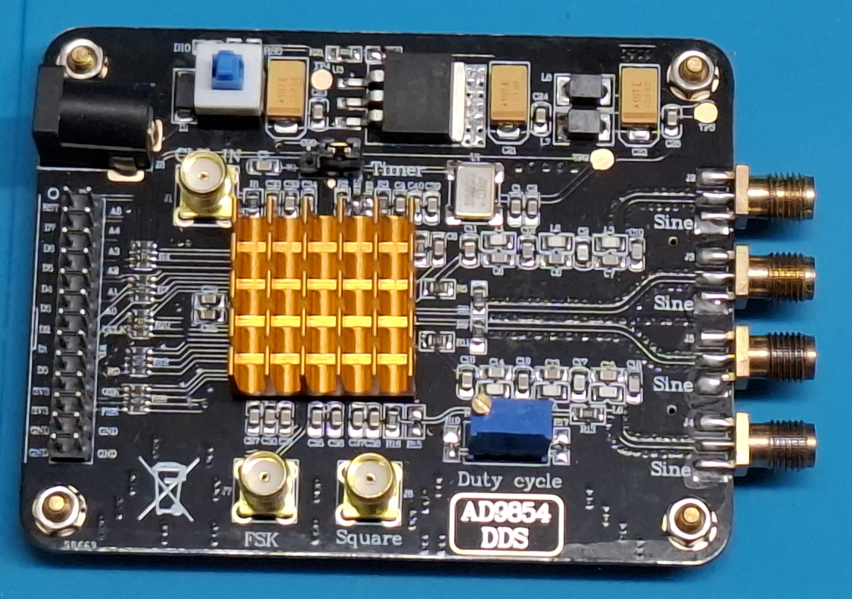
AD9854
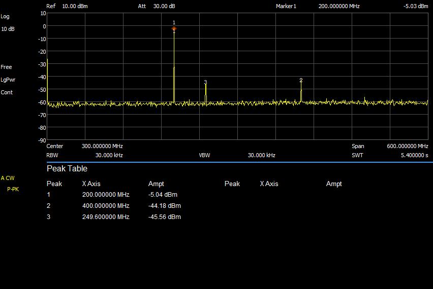
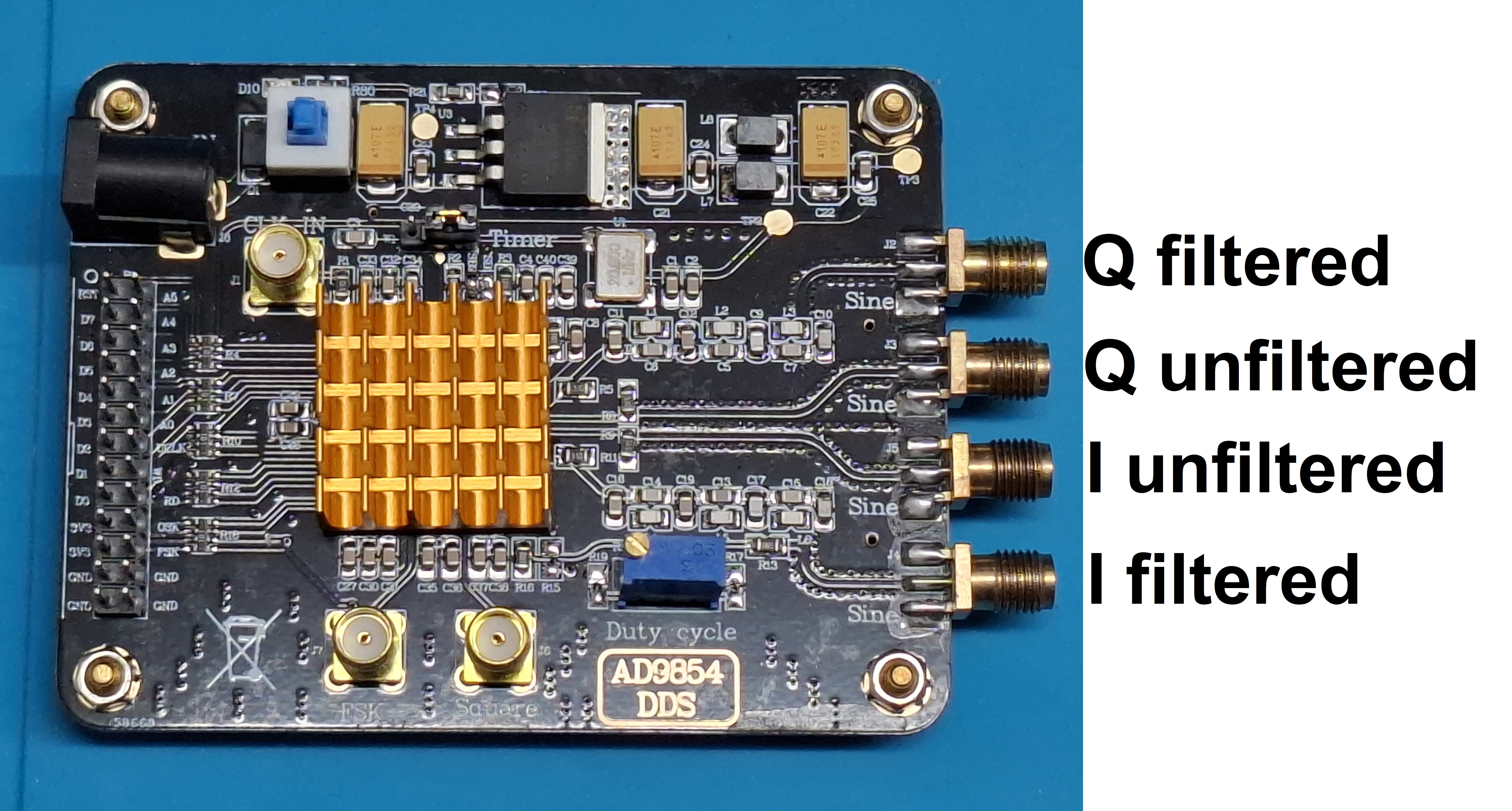
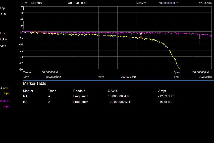
The AD9854 module has four outputs, a differential I and differential Q channel. However, one side of each channel is filtered through a 100 MHz LC low pass filter on the board, so you can’t actually use the outputs differentially. But you do have the option to use I and Q channels, either filtered or unfiltered.
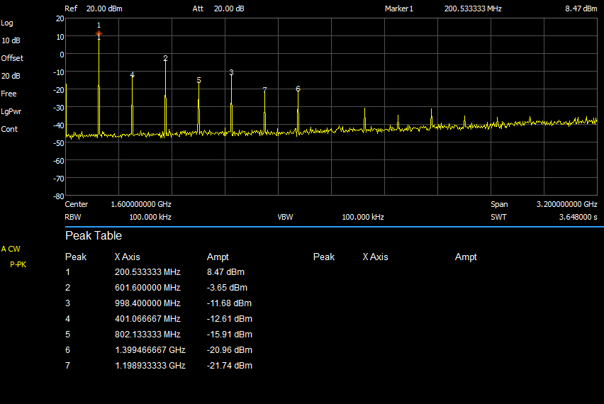
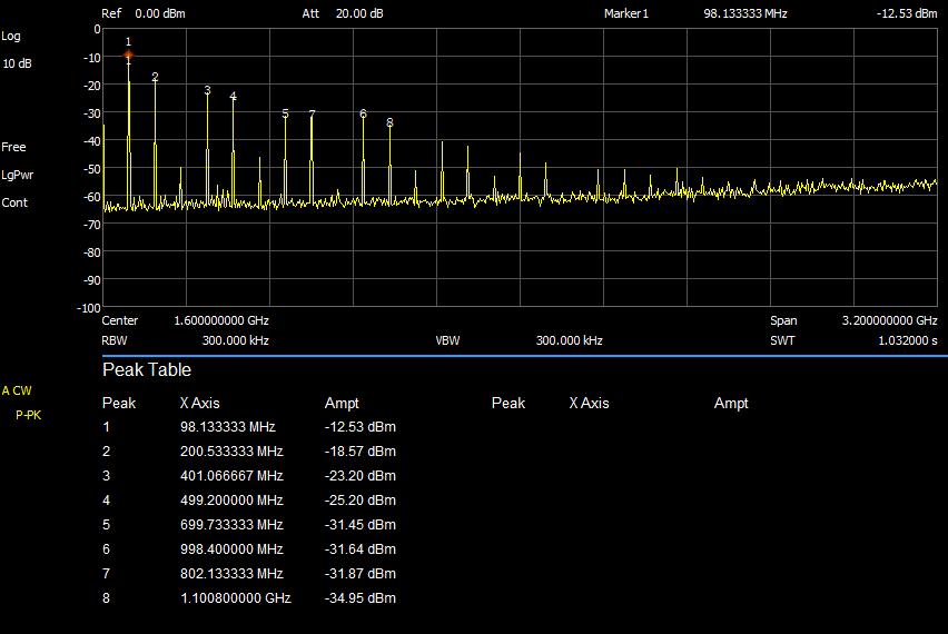
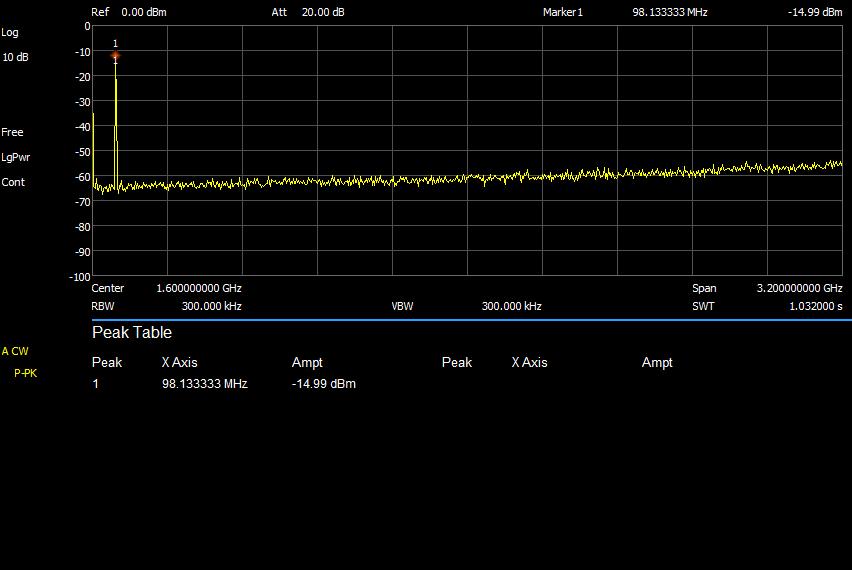
With higher output frequencies, we expectedly see much higher harmonic content, such that the filter is actually quite useful. With the filter, we can get a quite clean 100 MHz output. However, the filtered output is really only good up to around 100 MHz, because the amplitude drop off is quite steep after that. The chip draws around 800 mA during operation, which makes the heatsink absolutely necessary.
The board allows access to the parallel programming interface and I use a ribbon cable to connect it to the DDS Driver Board, then getting an output is as easy as setting a couple of registers:
|
|
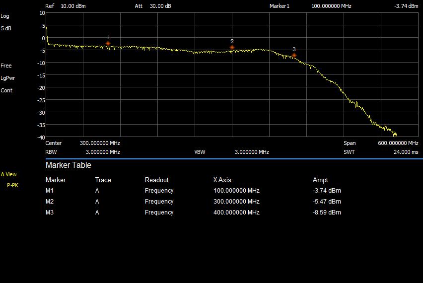
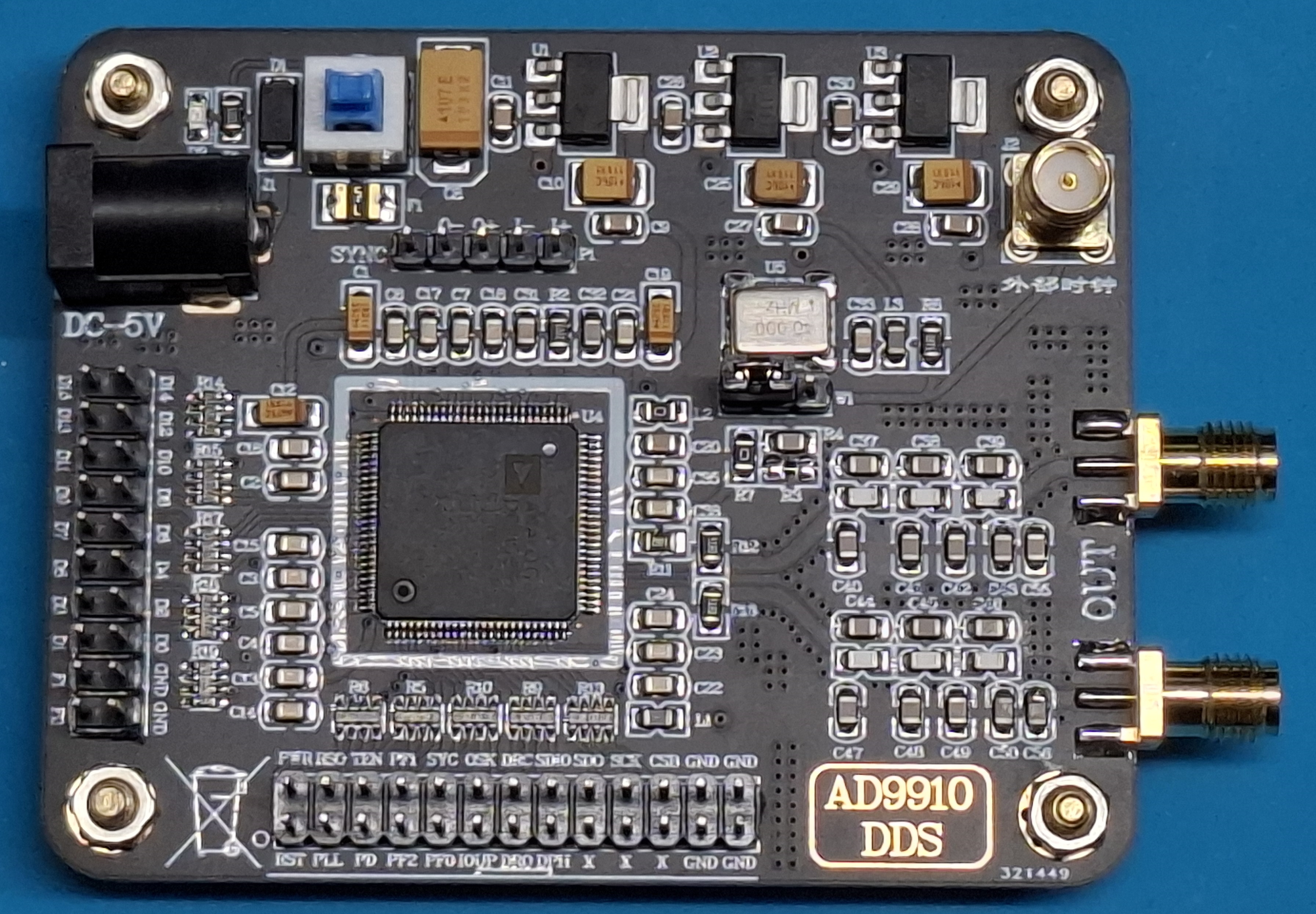
AD9910
The AD9910 is a more modern DDS chip than the AD9854. It has a differential output, which has a 400 MHz LC low pass filter on the module. The module generates quite a clean signal up to 400 MHz at around -5 dBm. I’m using the DDS driver board to connect to the serial interface of the board (STM32 source code). Not only has this module a much greater frequency range than the 9854, it also consumes much less power, around 200 mA in operation. If you don’t need the extra Q output that the 9854 provides, you should pick the 9910 instead.