Overview
When playing around with RF circuits, there comes a day where you’d want to digitize a signal, stream it to your PC/Laptop/Raspberry Pi and do the rest of the signal processing in the digital domain - this is basically the old SDR story. There are countless SDRs available now, even some relatively cheap ones like the original RTL-SDR. These SDRs have everything you need for the task in theory, but aren’t really suited for digitizing a low frequency (DC to ~50 MHz) baseband signal. This is because the typical SDR application involves an input signal at RF frequencies, and the SDRs are built around performing a downconversion mixing step on the input signal first. Additionally, the cheaper SDRs usually also have quite low baseband sample rates.
Options
When looking for ways to digitize a baseband signal to the PC, there are a couple of options:
- Sound Card (“free” because you already have it)
- ADC development boards (100s of €)
- Data Acquisition Cards (DAQ) (1000s of €)
- USB oscilloscopes (10s of €)
The sound card option is the simplest but audio ADCs have relatively low sample rates which makes this solution only suitable for very narrowband and well pre-filtered signals. There are a few ADC development boards but these typically require additional hardware, like an FPGA, to stream the data to the PC. I also found them to be quite expensive for the higher performance ADCs. Industrial DAQ cards are offered with high sample rate analog inputs and direct connection to the PC via PCIe; these would do the job well but are ridiculously expensive.
Finally, there’s the USB oscilloscopes, combining a simple frontend, an ADC, some memory and a USB interface. Here, it’s important to note that real time streaming of samples is not the normal mode of operation for these devices and therefore, it’s not always supported. If it is supported, the USB bandwidth can be an issue (USB 2 HS: up to 480 Mbit/s, USB 3.0: up to 5 Gbit/s). Another consideration is the ADC resolution: Oscilloscopes typically have a number of programmable attenuators and/or amplifiers in their frontend which are controlled through the “voltage scale” knob. This means that they can get away with less dynamic range on the ADC and that’s why 8 bit ADCs are commonplace, even in better oscilloscopes, while SDRs nowadays mostly use 10 or 12 bit, although some like the original RTL-SDR and the HackRF one are also using 8 bit ADCs.
Suitable USB oscilloscopes
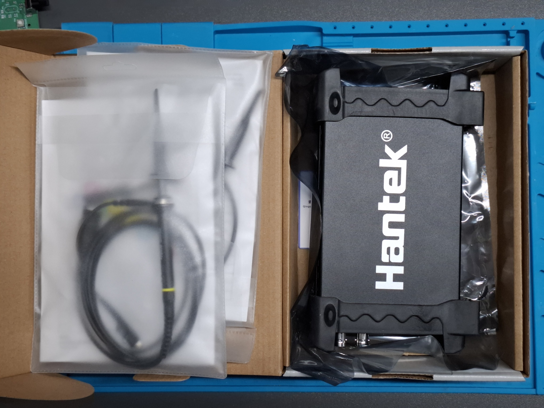
In the end, the USB oscilloscope was the only suitable solution in terms of cost and performance. They are produced and sold in quantities, which has led to a few interesting low-cost options on AliExpress/eBay etc. Out of those, the most interesting ones are a group of similar / cloned designs built around an Cypress / Infineon FX2LP USB Chip, because Open Source Firmware and Software exists for them, making them much easier to repurpose. Out of these, I ended up with a Hantek 6022BE:
- 2 Channels
- 48 MSPS, 8 bit ADC. Higher bandwidth, more expensive versions exist but were not interesting to me because 48 MSPS is already getting close to the theoretical maximum of 480 MBit/s on USB 2.0 HS
- Supported by Open Source Software/Firmware: OpenHantek, sigrok
- Around 60€
Other devices based on the FX2LP chip that are compatible with the same firmware are listed here
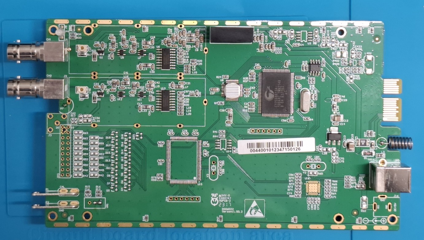
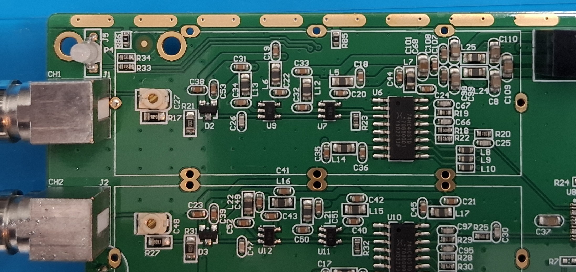
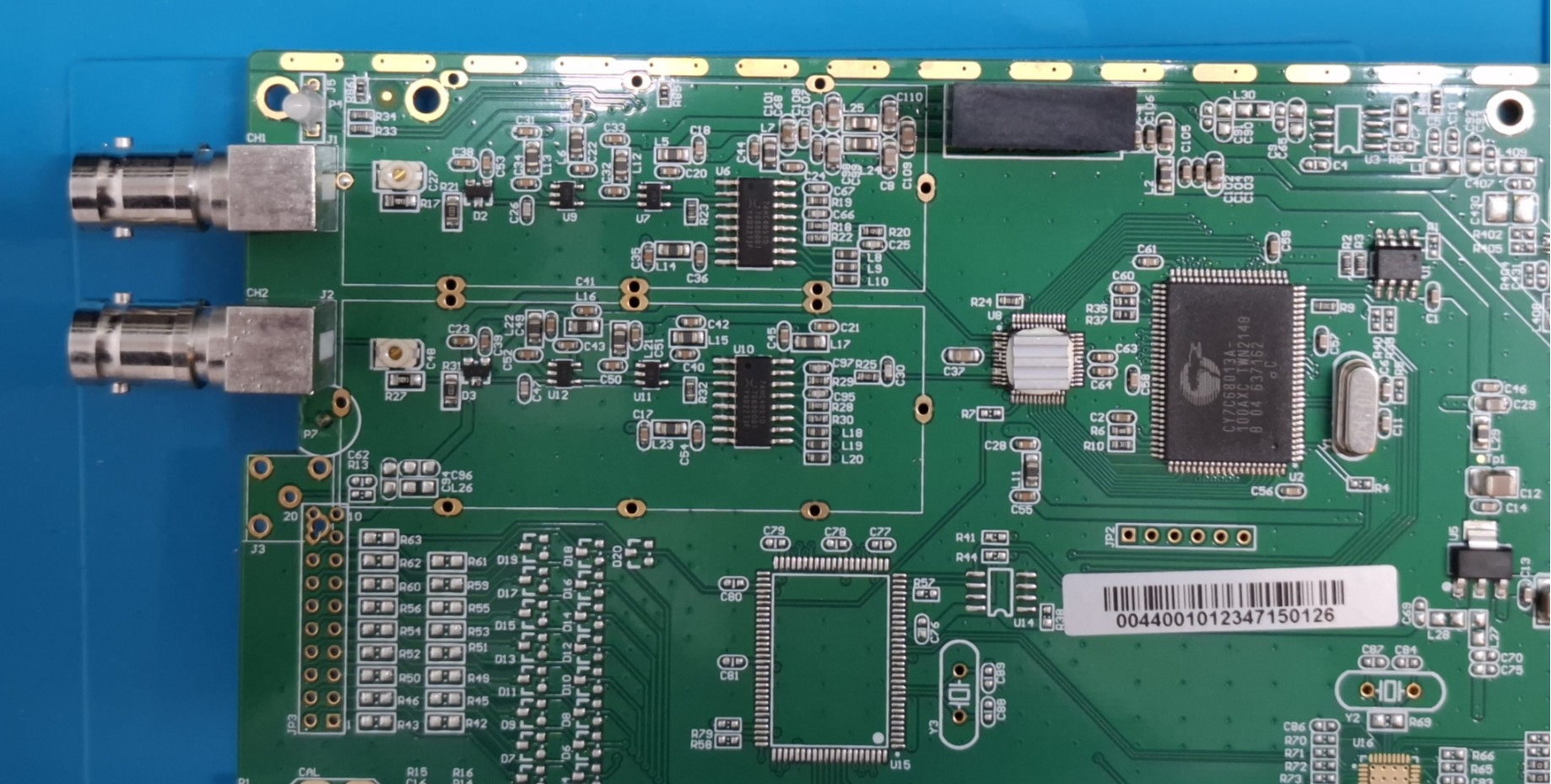
Input circuit

Hardware Modification
This modification is not necessary to get the sample source or FM receiver working and was only performed to get some better sensitivity on the ADC.
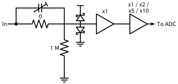
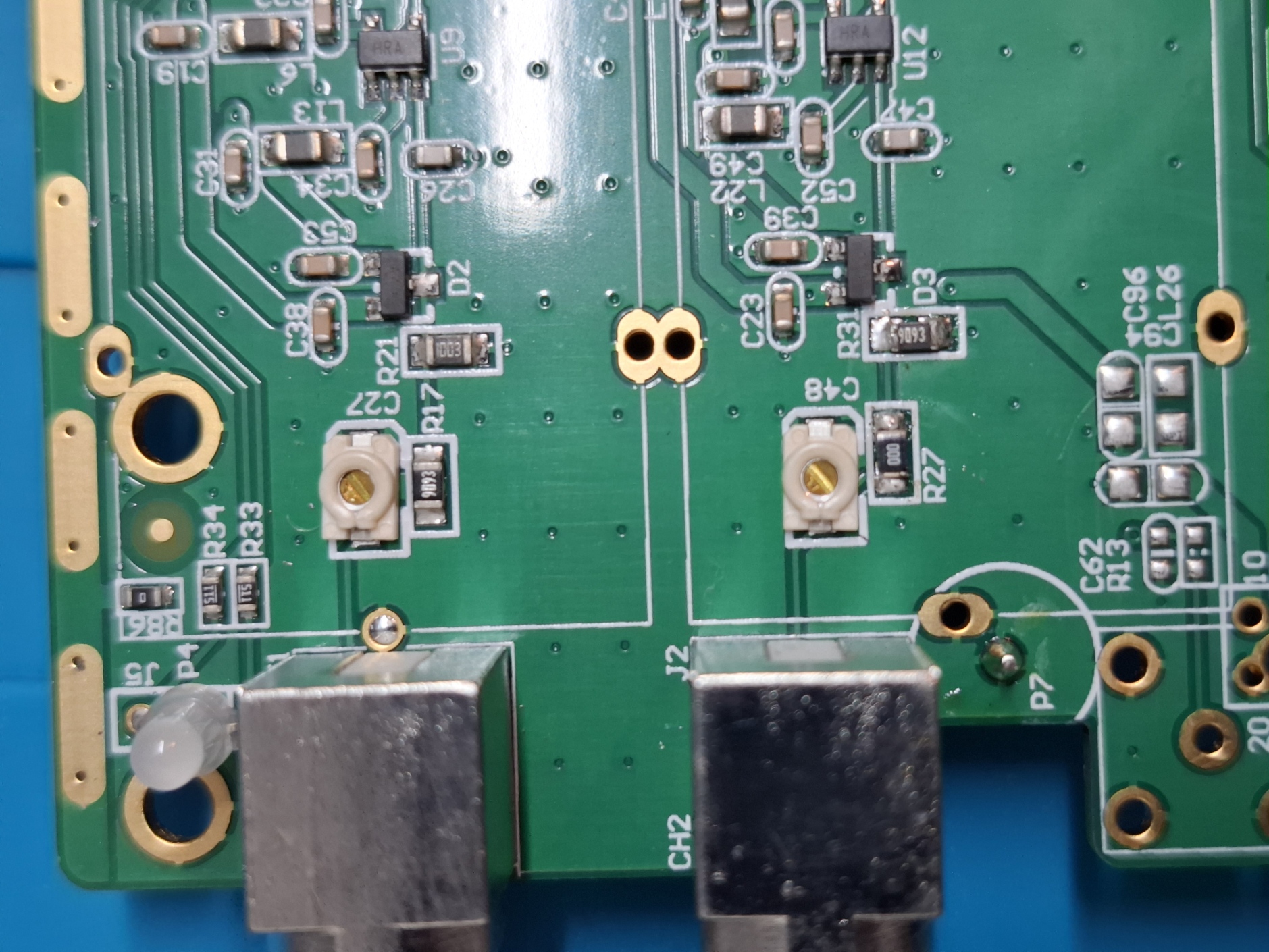
The stock input circuit is not ideal to sample small amplitude signals because of the fixed 1:10 attenuation, limiting the overall amplification to 1 (including the selectable gain amplifier) and the resolution to 4 mV. If the attenuator was removed, the resolution would be a much nicer 400 µV. I therefore modified the input circuit on CH1 by putting the 909 k resistor in place of the 100 k and putting 0 Ω in place of the original 909 k.
Courtesy of the Cypress FX2LP chip, the system can only sample either only CH1 or both CH1 and CH2, but never only CH2. This means that the fastest sampling is only possible on CH1. Thinking about it now, I probably should have made the modification on CH1 instead of CH2.
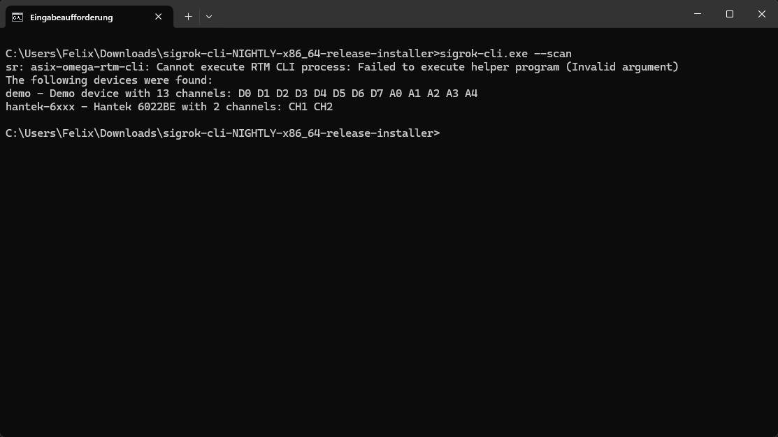
GNU Radio sample source
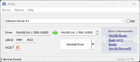
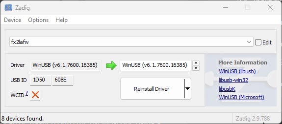
I’m using the open firmware fx2lafw for this project. This firmware can be flashed onto the oscilloscope using a tool like sigrok-cli (or fx2adc, see below). The firmware will only be present on the device until it’s power cycled though, meaning it returns to stock firmware after every use which can be nice if you also want to use it with the original software. On Windows, to use any of the open software or libraries, you have to make sure that the USB drivers for both the stock firmware (0x04b4 0x6022 for the Hantek 6022) and the fx2lafw (0x1d50 0x608e) are set to a libusb compatible driver.
Python Block
I first implemented the sample source as an embedded python block in GNU Radio. The advantage is that these blocks can be coded directly in the GNU Radio block diagram and require no dedicated building. The control interface of the fx2lafw firmware is very simple, we just have to set 3 control registers via control transfers and then trigger the conversion. From then on, we can read the sample data as bulk transfers from a dedicated usb endpoint. This can be implemented with pyusb in a few lines:
|
|

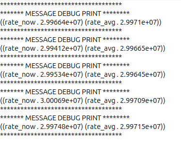
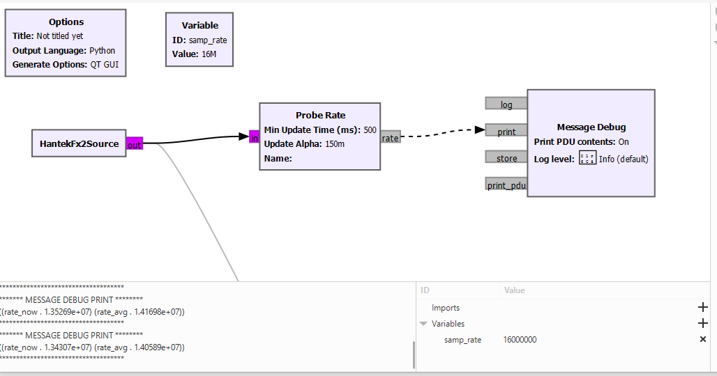
The disadvantage of this approach is that python blocks are pretty slow in GNU Radio and (at least on my computer) this configuration can’t manage sample rates above 16 MSPS without dropping samples. We can test this easily by using the Probe Rate and Message Debug block, which will print the actual throughput in the console.
High Performance Block
The fx2adc library implements the USB communication and sample gathering logic for fx2lafw devices in C. It also provides a utility, fx2adc-test which measures the maximum sample rate through the device for the case of just data transfer without any processing. Using this utility, I can stream at the 30 MSPS setting without dropped samples. However, when trying to stream at the 48 MSPS setting, it’s dropping some samples. This result seems to be quite close to the general performance of the FX2LP chip, that others have measured.
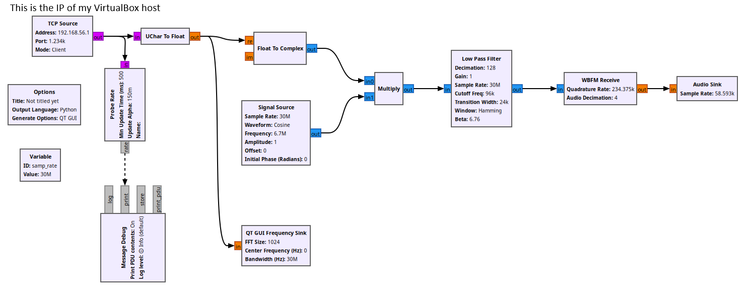
Another utility, fx2adc_tcp. spawns a TCP server and streams the sample to a client, e.g. the TCP Source block in GNU Radio. Using this setup, we can get the full 30 MSPS into GNU Radio.
The TCP Source GNU Radio block does not work on Windows. Because of this, I run GNU Radio in a VirtualBox Ubuntu VM. However, the VirtualBox USB driver seems too slow to accept the fx2lafw samples at full speed. The solution is to run fx2adc_tcp on your Windows host and connecting the TCP Source block from within the virtual machine.
Simple FM Receiver
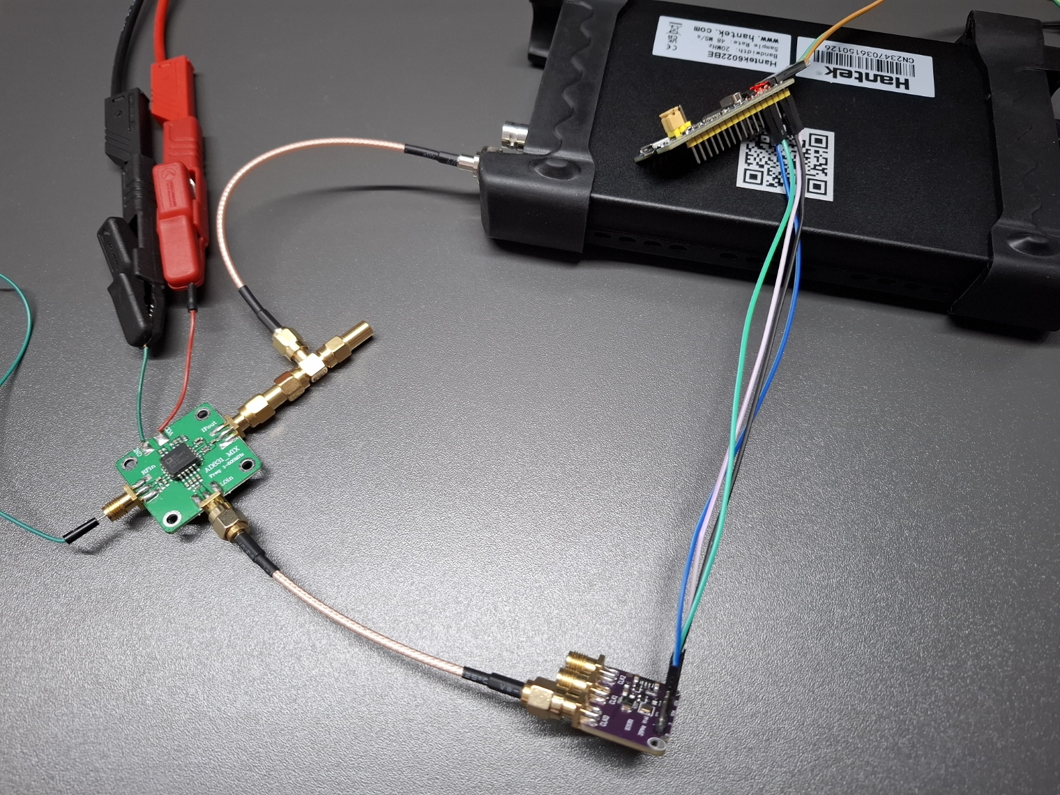
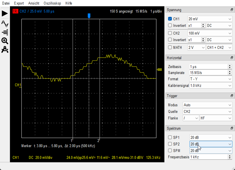
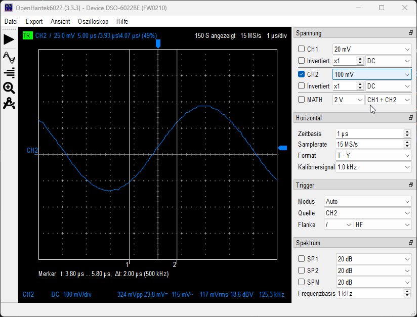
To test the usability as an IF/baseband digitizer, I set up a small “analog frontend” consisting of an AD831 active mixer module and an Si5351 module as the LO. I program the Si5351 to output 110 MHz using an STM32 Bluepill. The RF input of the AD831 just has some cable attached to the core conductor of the SMA plug as an antenna. The output of the mixer is terminated in 50 Ω and tapped to the USB oscilloscope.
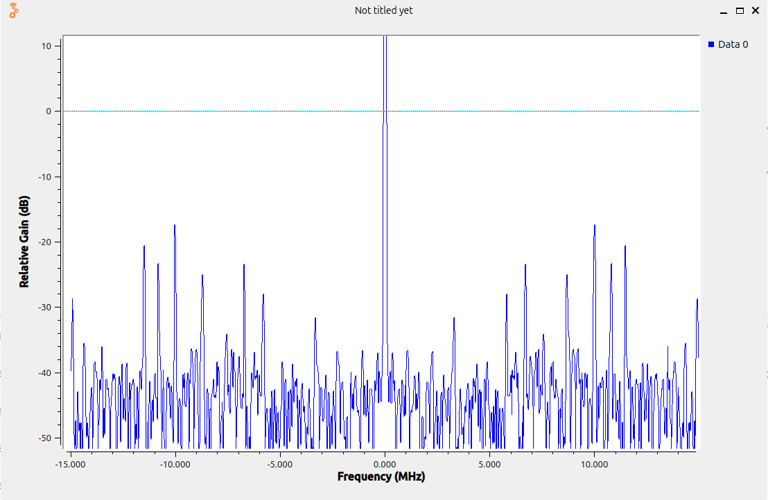
I picked 110 MHz for the LO because this is the upper end of the public FM broadcasting range here and I expect no mirror signals from 110 - 125 MHz, allowing me to use the left half of the spectrum (i.e. 95 - 110 MHz) well without additional filtering in the frontend. I’m able to pick up a few stations in this range and demodulate them clearly, even on the stock CH1 of the scope.